Hux Broadcast Signal Conditioner
Automatically corrects program phase reversal and single channel loss.
What it does
The primary function of the Hux Broadcast Signal Conditioner is to monitor and automatically correct sustained phase errors detected between the left and right input channels. These phase errors if untreated would cause program loss to mono destinations. The unit also monitors the input signals for a left input or a right input program loss. Should the unit detect that one input is missing it will switch the remaining good program input to both outputs until the defect is corrected, during this time the missing input is muted. Should the unit detect a total program loss it will indefinitely "hold" the last mode selected until program is restored.
The unit is best placed in the station signal chain before any AGC (automatic gain control) devices. Some AGC devices will react strangely if confronted with phase reversed material or material missing one audio channel. The Hux Broadcast Signal Conditioner automatically cures phase reverse and single channel loss problems so it makes sense to place it first in the signal processing chain.
How it works
Care has been taken to ensure that the audio signal path is short, clean and transparent. The unit is essentially DC coupled from input to output as the audio signal passes through only one capacitor on its journey. The audio signal path uses an instrumentation grade front end, the signal is then sent via a capacitor to a bank of SSM audio switching devices before being fed into summing amplifiers which form part of the balanced output driver circuits.
The internal audio switching and signal detector circuits operate at unity gain 6dB below the external balanced signal level. This high headroom approach ensures that internal signal clipping is not possible before external clipping and that the signal detectors can not be fooled by extreme signal levels.
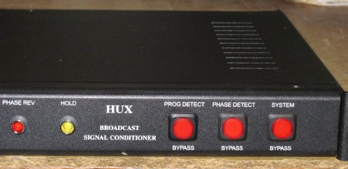
The signal detectors are based on simple and reliable analogue circuits. The detector thresholds are front panel adjustable via multi-turn trimpots. The front panel has sniff outputs for the program detectors (a common sniff and trim for left and right prog detect) and the phase reverse detector. The DC voltage on the relevant sniff port relates directly to the audio signal level, i.e. a DC level of 0.775 volts indicates that the threshold is set to 0dBu. In practice the thresholds are normally set to 90mV which is the same as -20dBu.The phase detector constantly compares the sum of the left and right inputs with the difference signal. The phase detector threshold trimpot adds a bias to the phase detector that ensures that the circuit always assumes that the program is "in phase" unless the difference signal exceeds the sum signal by more than the bias voltage at any given input level.
The detector circuits create three outputs when normal stereo inputs are fed into the unit, Left OK, Right OK and Phase OK, these outputs are fed into a PIC device which has been custom programmed for the job at hand. The PIC has adjustable delay times for sensing left or right program loss and phase reverse, the total program loss or "hold" delay is always half the left or right loss delay time. Importantly the PIC includes a hysteresis to prevent momentary "in phase" segments of an "out of phase" program from false triggering the unit back to normal mode if sustained phase reverse has been detected, the hysteresis has an identical delay time to the phase error detect time.
The PIC device drives the audio switching electronics to control Left to Left, Left to Right, Right to Right, Right to Left and Phase Reverse to Right modes. The PIC also controls the front panel status LED's. Whenever the PIC detects an error and is timing out before changing state it will flash the relevant front panel status LED as a warning of the action about to take place. Once the time out period has elapsed the PIC will activate the relevant SSM audio switching device and light the associated LED. In the unlikely event that the PIC device should fail, pull up and pull down resistors are fitted to ensure that Left to Left and Right to Right operation is always the default condition.
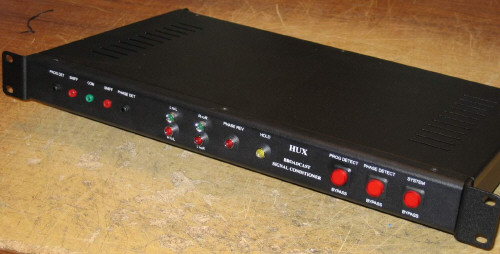
Included on the front panel is a program detect bypass switch, a phase detect bypass switch and a hard wire system bypass switch to enable the operator to manually override the Hux Broadcast Signal Conditioner functions if need be.